

Recently, flat-panel displays have become more popular because of their widespread use in portable electronics. We find thin-panel displays in many modern home appliances, making them the best alternative to the old CRT displays.
These displays are substantially smaller, lighter, and more portable than standard TVs and monitors. As a result, businesses worldwide are witnessing a surge in their demand.
Likewise, increased demand for handheld electronic devices has also contributed to the recent boom in display production.
Thus, companies must foster an atmosphere where the quality of their display will be exceptional. Maintaining high quality in the production line requires diligent effort, close attention to detail, and advanced inspection tools.
As a result, the flat-panel display (FPD) industry is placing a greater emphasis on module-level fault identification. Companies now use highly-advanced industrial lenses at different stages of LCM production. Using machine vision technologies in creating displays allows for greater output.
In this post, we’ll discuss the applications of industrial lenses that can find flaws at the module level.
What Is Lcm Segment in the Fpd Industry?
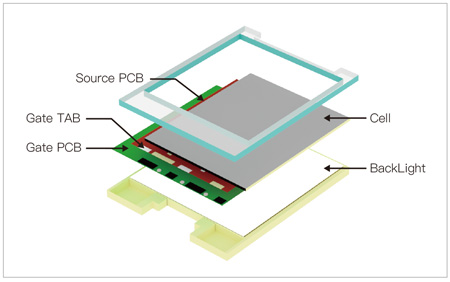
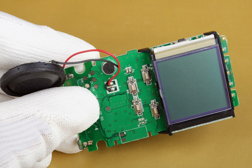
The LCM is essentially just a display and backlight combined. Different electronic components, such as ICs, backlight sources, and structural elements of a liquid crystal display, are assembled in this module.
For many applications in automotive, display, 3C, medical, and other industries, panels often undergo a process known as liquid crystal module (LCM) manufacturing. We call it the panels’ backend procedure because it occurs before the actual LCD production begins.
LCM is a method for assembling displays by combining LCD panels, driving ICs, control ICs, PCBs, backlights, and other crucial components. It also comprises a printed circuit board (PCB) as an electrical connector for the LCD controller IC.
Investments required for LCM processes are not as large as those for panel manufacturing. Besides, the LCM processes are more varied, requiring a variety of shapes and styles for various uses.
LCM factories can provide both smaller production runs and a larger range of services than panel manufacturers specializing in a specific good. Due to their unique characteristics and the high-profit margins associated with panel production, traditional panel manufacturers were reluctant to participate in LCM manufacturing.
However, panel makers are now investing in LCM factories or expanding current ones to meet rising demand and maintain profitability.
In-line inspection of LCMs is a reliable method for checking their quality and regulating production without interrupting the process. When LCMs are manufactured for high-end applications, the panels are examined again as a final quality control step, even if they have already passed inspection during earlier production processes.
LCM inspection finds various flaws, such as scratches, dents, bubbles, inclusions, lamination, and edge chip flaws.
An Overview of the TFT-LCD Process
Components such as the circuit board, driver IC, and backlight units must first pass through several stages to create an LCD Module.
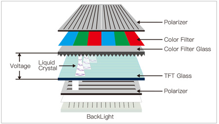
To further understand the TFT-LCD module, we can break it down into different layers as below. However, these layers are created from a product’s point of view.
- The backlight unit
- The electrical system
- The light-and-color control system
But from the perspective of the production process, the light and color control system becomes the first step. Thus, we can distribute TFT-LCD processes in the below three layers.
- Array Process
- Cell Process
- Module Process
The first two stages include creating the light and color control system. The last process involves assembling the LCD panel.
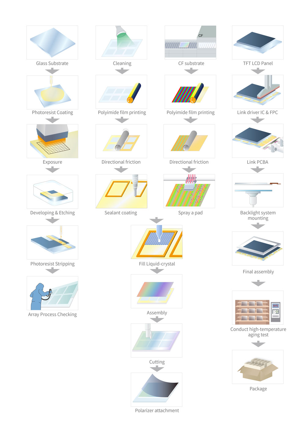
Array Process
The first stage aims to create a substrate suitable for use in thin-film transistors (TFTs) and color filters (CFs).
The process of a TFT array is quite identical to that of a semiconductor. This array process consists of many small tasks, such as:
– Cleaning
– Coating
– Improving photoresist
– Development
– Etching
– Clearing the photoresist, etc.
Cell Layer Process
The output from the prior process serves as the top and bottom substrates here. Also, the method involves dripping liquid crystal in between the two and then bonding them together. The resulting piece of glass is nothing but the LCD panel.
The same LCD manufacturer usually completes the array and cell layer procedures.
Module Process
After cutting the LCD panel, manufacturers of LCMs bind the backlight unit and other electrical components onto this panel before securing it with a frame.
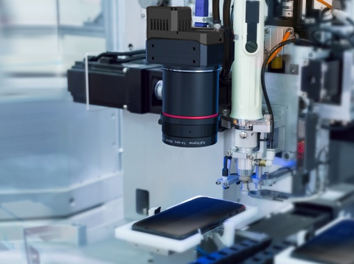
What Characteristics of Vision Devices Are Required in the LCM Stage?
While line scans are often used in the initial phases, area scan cameras take the front stage in the LCM phase. That’s because line scans are insufficient for detecting the faults present at the LCM stage, which often need imaging with multi-directional and multi-angle light sources.
Large area scan cameras are often used for appearance inspection. Large format lenses are in great demand because of the widespread usage of 71M/151M cameras in the LCM stage.
High focal length FA lenses are often used for panel inspection because this process often requires a long working distance.
Moreover, measurement tasks are often required during the LCM stage’s automated COF/COG bonding and positioning inspection. Due to space and height differences of the product, telecentric lenses are thus often utilized throughout the process. Internally coaxial telecentric lenses with high depth of field and adjustable aperture are often the best option due to space and height variances of the product.
The final inspection often employs many C-mount cameras to preserve inspection flexibility and quality. The product contrast is poor at this stage of inspection.
Thus, high-intensity light sources and high-resolution C-mount FA lenses are necessary. We must note that lens resolution is of the utmost importance here.
Lens Characteristics for Vision Inspection in the TFT-LCD Process
| Machine Vision Component | Application | Characteristics | Condition | Advantage |
|---|---|---|---|---|
| Lens | Positioning | Working Distance | >200mm | Avoid interference with the conveying mechanism. |
| 0.8~1.5x | Meet the size of the cross mark and the standard offset. | |||
| >0.4mm | The general difference in glass thickness is 0.3mm. | |||
| Rough Alignment | 0.3M/1.3M | Low alignment accuracy is acceptable, Require high speed alignment. | ||
| 5M | Requires High Accuracy | |||
| OCR Inspection | Focal Length | 35mm+ 2x magnification. | Small field of view and high precision. | |
| >80lp/mm | The poor contrast of the product requires a high-resolution lens to increase sharpness. | |||
| >2MP | There are certain requirements for resolution. | |||
| Micro AOI | Focal Length | 16~35mm | Different focal length lenses may be matched with the camera. | |
| High Speed | 0.3M | High-speed detection is required for machine speeds greater than 240 km/h. | ||
| 1.3~2.0MP | During the stage of glass flowing into the machine, the speed is slower and a higher resolution is required. |
| Process | Machine Vision Component | Specification Requirements |
|---|---|---|
| Array | Camera | 16K Linescan |
| Lens | Large Aperture, Low Distortion, 0.26~0.5x, Resolution 30um~70um |
|
| CF | Camera | 16K Linescan Color Camera |
| Lens | Large Aperture, Low Distortion, 1~2x, Resolution 7.5um~15um |
|
| Alignment Film | Camera | 16K Linescan Color Camera |
| Lens | Large Aperture, Low Distortion, 1~2x, Resolution 7.5um~15um |
|
| Frame adhesive | Camera | 16K Linescan 3.5um |
| PSVA | Camera | 6K Linescan Color Camera |
| Mura | Camera | 16K Linescan Camera |
| Lens | Large Aperture, Low Distortion, 0.2~0.3x, Resolution 75um~100um |
|
| Berr Check | Camera | 2K/4K Linescan, requires high speed for edge detection. |
| Lens | Linescan telecentric lens, requires low distortion for accurate measurement | |
| API | Camera | 16K Linescan Camera |
| Lens | Large Aperture, Low Distortion, 0.26~0.5x, Resolution 30um~70um |
What Type of Inspections Can Vision Devices Perform in Modern Lcm Production Processes?
As we saw above, telecentric lenses and high focal length FA lenses are mostly used in LCM production processes. Let’s check out at what stages we need them.
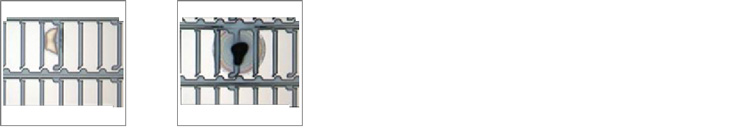
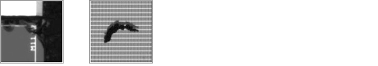
Micro AOI – Edge and Chip Detection
Glass can break, peel at the edges, or shatter into chips during the handling, transfer, and transportation processes. If this keeps happening, the glass may shatter all over the factory’s machinery and create contamination and waste.
LCD AOI Inspection – Array
Defects in the pattern or mask can be found, as can contamination, PR residues, and openings or shorts in the circuit.
LCD AOI Inspection – CF (Color Filter)

Manufacturers can expand the critical dimension (CD) measuring system with the help of industrial lenses. So this expanded system can be used in the color filter process, which includes BM, RGB color film, ITO, MVA, PS, and INS.
LCD AOI Inspection – Alignment Film
After the alignment film coating in the Cell process, PI AOI can precisely identify coating flaws, including uneven coating and particles. It can identify flaws like PI shift and internal particles in the film, among others.
LCD AOI Inspection – Frame Bonding Process
During frame bonding, vision devices can identify flaws such as Au shift, seal shift, internal particles in the film, and more.
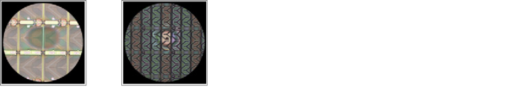
LCD AOI Inspection – PSVA

Vision devices can help detect liquid crystal abnormalities such as Mura, liquid crystal abnormalities, or foreign materials mixed in. With this, the manufacturer gets an accurate analysis of the measured data for brightness, grayscale contrast, and response time.
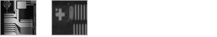
LCD AOI Inspection – Mura

This inspection is perfect for LCD final inspection, color filter inspection, TP inspection, and the Array process.
The word Mura effect is often used to present displays that are not perfectly uniform because of insufficient screen lighting. This test can identify pixels that are darker or brighter than their surroundings.
The FPC contacts on the lighting test fixture must be lined up with the ITO lines on the panel terminals to perform these tests. The technicians must appropriately align, press, and electrify it for a conductive lighting test.
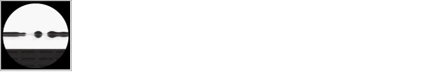
LCD AOI Inspection – Glass Appearance After Cutting (Burr Check)
Vision devices now allow for pre-bias examination of huge glass. It can find flaws like burrs, cracking, and other cutting defects.
LCD/LCM AOI Inspection – Light on Test

Light on simulation detection can be performed by API both before and after bias attachment on glass surfaces. Uneven grayscale (Mura), bright/dark areas, and bright/dark lines are just some of the flaws it can detect.
LCM AOI Inspection – PCBI Appearance
Accurate identification of flaws, including scratches, dents, and stains, is performed after COG/COF lamination.
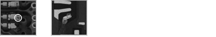
LCM AOI Inspection – Conductive Particle
The CCD is inspected using the conductive particle inspection process. This process guarantees proper particle distribution and attachment position.
Comparing Different Methods of LCM Defect Detection
Defect detection in TFT-LCD displays serves three primary functions.
- To start, it’s used for the analytical study of defects, which helps pinpoint general issues and their root causes so that you can strengthen any weak spots in the structure’s design or production process.
- The second function is correcting defects.
- Third, it removes defective goods. A defective TFT-LCD screen attached to a driving circuit can ruin the product. Thus, inspection saves companies from wasting the driving circuit.
Below we will discuss three main detection methods – manual, electrical, and optical measurement.
Manual
Manual detection requires evaluating each LCD screen individually to see whether it has Mura defects. This defect detection method is flexible as it works well with screens of many shapes and sizes.
Nowadays, some companies avoid this approach since it has numerous adverse drawbacks, including a poor detection rate. As a result, manual defect detection is labor-intensive, time-consuming, and less efficient.
Electrical Measurement

Although the electrical measurement technique fulfills certain efficiency criteria with numerous other benefits, it also has significant limitations.
This method is suitable for detecting electrically-induced point and line defects. However, it may not suit a wide range of non-electrical Mura defects. Besides, this approach takes a long time and yields inaccurate results regarding defect type and location.
Optical Inspection Based on Machine Vision
The standard and most widely used technique for detecting Mura defects is the optical measurement approach based on machine vision. Moreover, this method reduces the time needed to find Mura defects in LCDs.
It can detect and categorize multiple Mura defects without limitations. Furthermore, it is a noncontact detection approach with high efficiency and accuracy, eliminating several disadvantages of manual detection.
However, there is just one drawback of the optical inspection method. It often needs high labor and equipment costs and requires specialized personnel to operate.
So it is clear from this comparison that the optical measuring approach based on machine vision has several benefits over the manual detection approach, which has many drawbacks.
Production plants often use industrial lenses with varying degrees of magnification, focal lengths, and other characteristics. Industrial lenses play a crucial role in machine vision systems.
They may directly affect how the system processes algorithms and images. Choosing the right industrial lenses is crucial in developing a reliable vision system.
How to Choose the Right Industrial Lens for LCM Segment?
 |
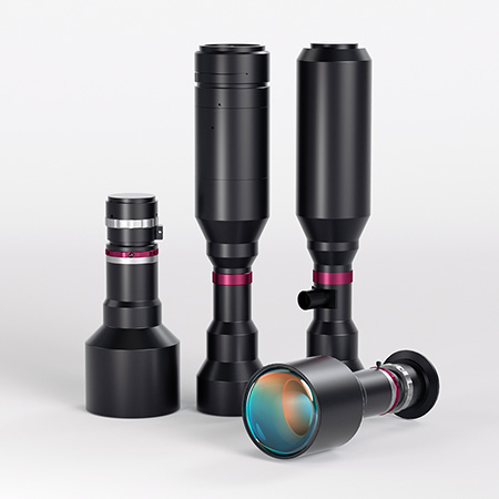 |
| 1.2″ Fixed Focal Length Lenses | 1.75″ M58-Mount Telecentric Lenses |
The sensor size and pixel size are crucial factors in choosing an appropriate lens. To prevent shading and vignetting, it is essential that the lens light the whole sensor region.
The lens’s ability to resolve pixel size is also a crucial factor. The lens should have a high optical resolution for more accurate and detailed results.
You must check the lens’s MTF, i.e., the Modulation Transfer Function. It describes the lens’ optical quality based on optical distortions. The subject’s details should be produced over around 4 pixels. It not only resolves them but also helps with definitive edge detection.
A perfect lens should replicate the original object in an image. The image should define the object in terms of dimension and brightness.
However, this much perfection is not achievable practically. MTF represents the degree of attenuation at any particular frequency. Every lens has a point where the MTF is zero. We call it the resolution limit.
Nevertheless, you can still choose a suitable lens designed for your particular application.
Types of Lenses
The purpose of any machine vision system is to record and analyze visual information. It helps to inspect physical attributes like the features and dimensions of an object.
Machine vision systems improve accuracy and productivity dramatically. However, this system is highly dependent on the quality of the input picture. Thus, you must select the appropriate type of lens that can deliver precise images suitable for the machine vision system.
There are different types of machine vision lenses to choose from because of the wide diversity of sensor types and resolutions. But we will discuss two commonly used types of lenses below.
Fixed Focal Length Lens
You can call them C-mount Lenses or Fixed Focal Length Lenses. Fixed focal length lenses are common in inspection and robotics applications.
These lenses feature imaging lens assemblies created with a fixed field of view. Even though they have a minimum working distance, their maximum working distance has no limits. It extends their performance limit to infinity.
Because of the lens’ fixed focal length, nearby objects will look bigger than those farther away. Fixed focal length lenses are available at VicoImaging in a broad range of specifications, including:
– Diameters
– Anti-reflection coatings
– Sensor coverage
– Resolving powers (MTF)
– Focal lengths
– Working distances
Automated machine vision applications benefit greatly from the compact design of our fixed focal length lenses.
Telecentric Lens
In telecentric lenses, light entering directly along the optic axis is used to form a picture. Object space, image space, and bilateral telecentricity are the three main types of telecentric lenses.
– Object-space telecentric lenses: The entry pupil of object-space telecentric lenses is at infinity.
– Image-space telecentric lenses: The exit pupil of image-space telecentric lenses is at infinity.
– Bilateral lenses: Both entry and exit pupils are at infinity in bilateral lenses.
Telecentric lenses are superior to endocentric lenses in terms of picture quality and consistency, since the magnification they provide is independent of the distance to the target.
What Are the Recent Developments in Industrial Lenses for the LCM Segment?
Machine vision is a rapidly developing and extensively accepted technology in various manufacturing environments. Here are four major developments in machine vision that can help you keep up with the ever-accelerating speed of the industry:
Machine Vision Lens Polarization
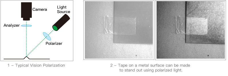
Several older cameras had polarization filters that worked only at certain angles of light. New technologies have made it possible to manufacture sensors by separating wire grids in an open layout on the chip.
It allows for far more efficiency and adaptability in light polarization. With these sensors, we can do things that were previously impossible.
The Growth of Computational Imaging
CI (Computational Imaging) allows acquiring and processing pictures differently. It combines computational methods with optical encoding.
CI offers improved precision, reliability, and productivity by further improving the machine vision systems’ current potential. Because of this, CI is already a standard part of machine vision in many factories.
Liquid Lens
As the size of camera pixels continues to shrink, lens manufacturers are standing ahead to produce superior machine vision lenses.
Lens manufacturers are working to improve the speed and quality of industrial machine vision lenses. They have the challenge of producing superior lenses without altering the mechanism of traditional lenses.
More Advanced Optics
Choosing relatively simple optical components like industrial machine vision lenses might become difficult in the near future.
We can blame the improved sensitivity and resolution of current image sensors for this. Modern sensors can produce smaller or bigger pixels. Thus, other optical equipment must compensate for it.
Changes in the above four areas will significantly affect the industrial machine vision lens market in the upcoming years. Both lens manufacturers and buyers will have to keep up with the ever-evolving machine vision sector.
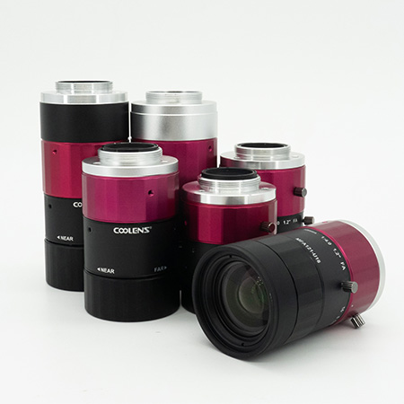
Why Choose Coolens Industrial Lenses in the LCM Segment of the FPD Industry?
We have discussed different aspects of the LCM segment so far. As you can see, the success of any machine vision system depends on the type of lens you use.
If you are looking for high-quality lenses for the LCM Segment of the FPD industry, you can choose lenses designed by Coolens.
Enhanced Productivity
Coolens lenses provide higher levels of accuracy and precision. It leads to fewer production mistakes, improved defect detection rate, and higher output.
High Resolution Offering Exceptional Clarity
The contrast transfer function (CTF) is a common metric for measuring image resolution. It provides a quantitative assessment of the contrast between the image sensor’s spatial frequencies.
Some machine vision integrators use a group of low-quality, low-resolution lenses, which results in blurry and unclear pictures. Industrial telecentric lenses provide high-resolution imaging from even the smallest pixel image sensors.
Increased Efficiency
Coolens lenses allow for more efficient and accurate manufacturing processes. Our lenses can help you reduce production time and costs.
Low Distortion
The distortion coefficient is the ratio of the image sensor’s physical size to the resulting picture’s size. A distortion of more than 2% is common in ordinary industrial lenses. It may have a considerable impact on the accuracy of the measurement.
On the other hand, industrial telecentric lenses are subject to pass stringent manufacturing and quality testing to ensure a distortion rate of less than 0.1%.
Improved Quality
High-quality imaging and measuring abilities offered by Coolens lenses guarantee that the LCDs will be of the correct dimensions, including flatness, size, and thickness.
No Perspective Error
In metrology applications requiring exact linear measurements, seeing the item from its standard front is typically required. Furthermore, the time gap between measurements is dynamic, making it difficult to position various mechanical elements properly. Thus, it becomes difficult to capture an accurate image of the object.
To avoid any of these issues, just position the entrance pupil of your industrial telecentric lens to infinity before you begin your imaging process. It will only accept the main ray in a parallel direction to the optical axis.
Ultra-Wide Depth of Field
Industrial lenses often improve the depth of field by using aperture and magnification.
Also, the image does not change even after moving the object within a specific distance range. It means the magnification stays constant and unchanged.
Final Thoughts!
Flat Panel Display (FPD) is the fastest-growing industry these days. It plays a crucial role in most modern electronic devices, including mobile phones, TVs, computers, etc.
Liquid Crystal Module (LCM) production is an important segment of the FPD industry. Thus, we have covered all vital elements impacting LCM systems.
Lenses have certain features and characteristics, and knowing them can help you choose the right lens for your needs. LCM production lines often have high-temperature and high-pressure conditions. Moreover, the lens should offer precise results without getting affected by harsh surroundings.
Using industrial lenses at different stages of LCM manufacturing has proven to be an effective solution. By utilizing the right lenses, manufacturers can now identify and correct any defects or inconsistencies in the production process. In short, LCM manufacturing will continue to evolve and improve with the help of these powerful tools.
Panel processing has always been a highly automated production process. It has many machine vision applications, including adhesive and water droplet residue detection, confirming polarizer positioning, etc.
However, explaining all these machine vision inspections in a single post is challenging. In fact, many manufacturers don’t count them under AOI applications. That’s because these inspection processes are not universal. Thus, they will always be termed as modifications or additions to the inspection equipment.
