
The Application of COOLENS Industrial Lenses in the LCM Segment of the FPD Industry
Introduction:
The FPD (Flat Panel Display) industry is a rapidly growing sector with a wide range of applications, from televisions and computers to mobile devices and automobiles. One important segment of this industry is the LCM (Liquid Crystal Module) production process, where COOLENS industrial lenses play a crucial role.
Advantages of COOLENS Lenses in LCM Production:
The use of COOLENS industrial lenses in the LCM production process offers several advantages. Firstly, the high precision and clarity of the lenses ensure that the liquid crystal layers are accurately aligned and functioning properly. This results in higher-quality and more consistent displays. Secondly, the durability and reliability of COOLENS lenses ensure that they can withstand the high-temperature and high-pressure conditions present during LCM production. This reduces the risk of lens damage or failure, leading to reduced production downtime and lower maintenance costs.
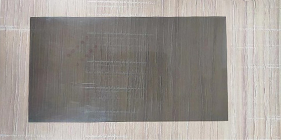
The Application of Cutting Stage in LCM Production
Introduction:
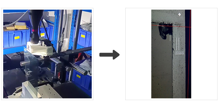
In the LCM (Liquid Crystal Module) production process, the large flat panel out of the previous process needs to be cut into smaller pieces with specific shapes and sizes that fit the actual application. This includes cutting off the CF layer to expose the TFT layer and ITO lines in the terminal area. The main cutting technologies include wheel cutting, CNC grinding, and laser cutting, with laser cutting having the highest resolution requirement, followed by CNC grinding. Both of these cutting methods require high-precision visual assistance for location. Laser cutting is the main cutting method used in OLED products, while wheel cutting and CNC grinding are becoming less prevalent in traditional LCD processes.
In conclusion, the cutting technology used depends on the required resolution and precision, with laser cutting being the most widely used method in OLED production, and wheel cutting and CNC grinding being used less frequently in traditional LCD processes. Regardless of the method used, high-precision visual assistance is necessary for accurate location during the cutting process.
Imaging System Configuration:
 |
 |
|
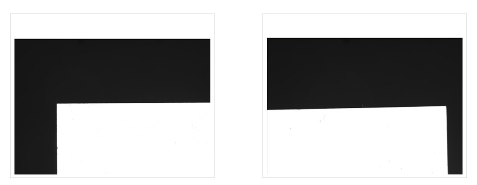
For laser cutting:
a 6MP 1/1.8″ camera, a WWH10-108ATV3, and a white external coaxial light.
|
For CNC grinding:
a 6MP 1/1.8″ camera, a WWH10-180AT, and a white external coaxial light.
Resolution: 0.02mm
|
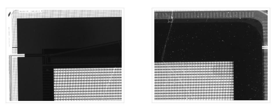
LCM – Post-Cutting Inspection Stage
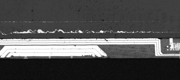
Application: This section primarily checks for any defects such as cracking around the edges of the product after the cutting process, with a focus on checking if the terminal area is damaged or has any foreign objects. This is to prevent defective products from flowing into the next process of attaching the polarizer, which would result in material waste, as well as to screen out any terminal abnormal products during lighting tests to improve test efficiency.
Imaging System Configuration:
- Camera: 2K 7um, 4K 8um line scan camera.
- Lens: 1-2X line scan Telecentric Lens with an angled prism and high-brightness coaxial light.
- Resolution: 3-7um/pixel.
- Key Point: This section requires high precision and speed, with extremely high brightness requirements for the light source. The lens also needs to balance high resolution and depth of field, requiring a well-balanced hardware solution.

COOLENS Advantage: COOLENS creatively customizes high-precision telecentric lenses for customers, along with high-precision imaging-level half-reflective prism modules. Compared to the traditional method of using a traditional lens with an angled prism and commen coaxial light, this saves installation space and solves the problem of image resolution being affected by using a common coaxial light half-mirror.
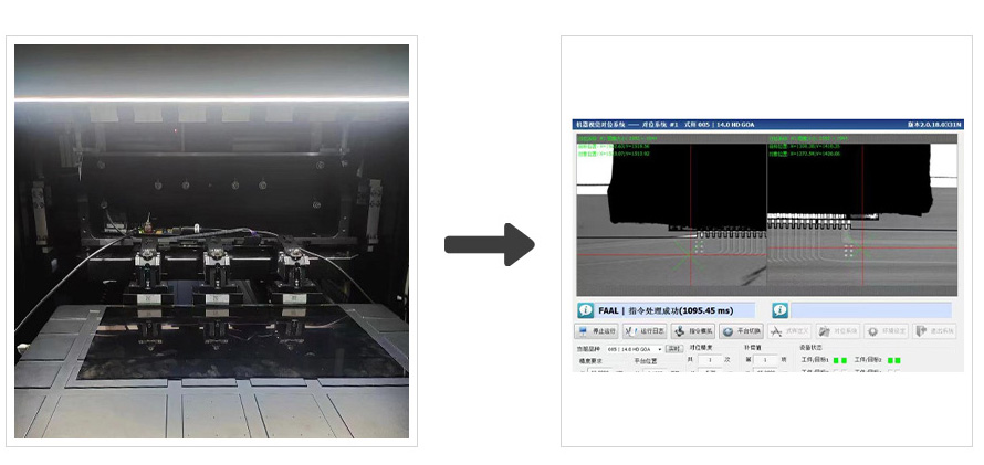
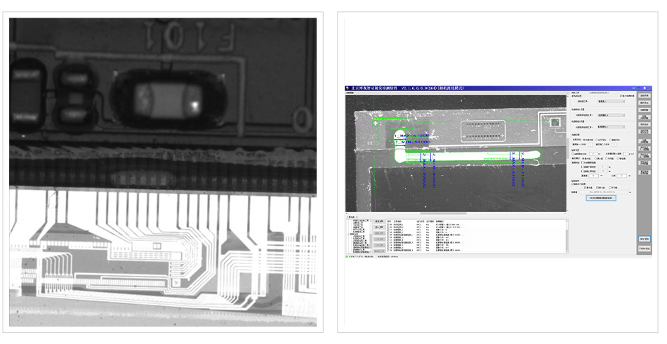
LCM —— CT1 Lighting Inspection Section
Application: Mainly used for the first time lighting API signal on/off detection before the panel is partially pasted after cutting. The lighting test of the panel is mainly divided into three parts: API electrical performance testing, appearance AOI inspection, and display screen Mura inspection. These three inspections require visual precise positioning of the FPC contacts on the lighting test fixture with the ITO lines on the panel terminals and then press-fitting and electrifying for a conductive lighting test.
Imaging System Configuration:
- For Press-fit positioning: 6MP 1/1.8″ cameras plus 0.8~1.5X telecentric lenses and ZZ prism mirrors with coaxial lights
- Positioning resolution: 0.02mm
- For Lighting detection: 71MP or 150MP high-pixel area scan cameras
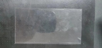
LCM-Polarizer Attachment Section
Application: This section is mainly used for attaching polarizers to the panels after cutting the LCD products. The polarizers for the front and back are 90 degrees apart and work with the twisted light from the liquid crystal to control the light display of each pixel electrode. The polarizers and the panel also need to be located using high-precision vision, and then a roller with a steel strip is used to achieve a bubble-free attachment to achieve a good display effect. OLED products only need to attach one polarizer because they are self-luminous.
Imaging System Configuration:
- For glass photography: 5.0MP 2/3″ cameras with 1x telecentric lens and white coaxial or infrared ring light
- For POL photography: 5.0MP 2/3″ cameras with 0.2 to 0.25x telecentric lens and blue coaxial light
- For post-attachment accuracy inspection: 5MP 2/3″ cameras with 0.4x telecentric lens and white half-ring light and infrared backlight
- Resolution: 0.05mm
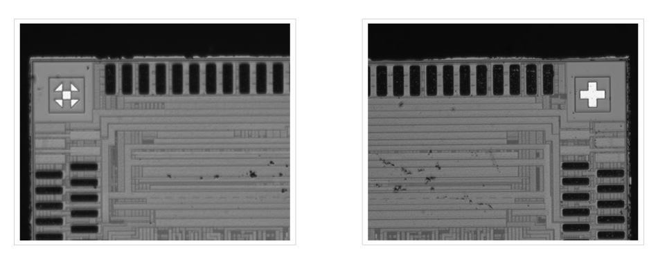
The LCM —— COG binding section
COG binding refers to the process of binding a chip to a glass substrate using chip on glass (COG) technology. In this process, the chip is attached to the glass substrate through an adhesive particle (ACF) by means of a hot press head. During the binding process, visual inspection is used to accurately locate the position of the chip on the glass substrate. Misalignment during the press process can cause short circuits, abnormal screen display, and other issues. As the screen resolution increases, the density of the circuits increases, leading to higher requirements for the accuracy of the binding process. The overall adhesive positioning resolution is up to 1~5um, which is the highest requirement among all the LCM packaging processes. The COG binding line requires visual inspection for glass substrate rough positioning and pre-press precise positioning, IC rough positioning and pre-press precise positioning, and press positioning, etc.
Imaging System Configuration:
- For glass substrate: 1.3MP 1/3″ camera with 0.5~0.8x telecentric lens with coaxial light
- For IC substrate: 1.3MP 1/3@ camera with 0.3~0.5 lens with coaxial light
- For COG pre-press positioning: (Resolution: 0.003mm)
- Camera: 1.3MP 1/3″
- Lens: WWL60-65CT
- Prism: SQ-ZL1.5L, SQ-ZL1.5R
- Lighting: White dot light source + custom red light source on prism

The LCM-FOG binding process
This process is a method of connecting the flexible printed circuit (FPC) to the glass substrate using the adhesive conductive particles (ACF) in order to make an electrical connection. The FOG process is similar to the COG (Chip on Glass) process and requires high precision vision positioning to align the FPC to the specific ITO (Indium Tin Oxide) circuit pattern on the glass. This allows the external control circuit signals to communicate with the LCD panel effectively. The whole FOG binding process involves vision requirements such as rough and precision positioning of the glass and FPC substrates, as well as final press positioning.
COOLENS’s contribution: COOLENS introduced the earliest Z-shaped and T-shaped non-standard eccentric lenses in 2008 for early manual binding equipment in China, breaking the blank in lens application in this field in China and helping domestic equipment manufacturers to replace the LCM segment equipment from Japan and South Korea. The application lens has a cumulative shipment of 100000+ units.
Imaging System Configuration:
- For glass substrate feeding: 1.3m 1/3″ camera and 0.5-0.8x telecentric lens with coaxial light.
- For FPC substrate feeding: 1.3m 1/3″ camera, 25mm lens and hole surface light or backlight.
- For COG pre-press positioning: (Resolution: 0.003mm)
- Camera: 1.3MP 1/3″
- Lens: WWL20-65CT
- Prisms: SQ-ZL1.5L, SQ-ZL1.5R
- Illumination: white point light source and custom red light source on the prism.

LCM Bonding Process:
Application: The bonding process used will vary depending on the product type, with different packaging requirements for wearable devices, smartphones, in-car displays, full-screen displays, etc. For example, medium-sized in-car displays use COB (IC directly bonded to PCB) and FOB (FPC bonded to PCB) bonding processes, while full-screen displays use COF (IC directly bonded to FPC) bonding processes, all using the same principle of using conductive particle adhesive and precise visual positioning and correction before being compressed using a hot press head. LCM bonding processes heavily utilize telecentric lenses with small fields of view, and are one of the largest applications for the early production of telecentric lenses.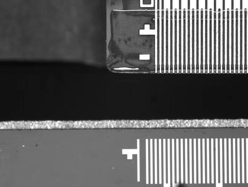
LCM – Dispensing & Dispensing Inspection
Application: Mainly used to apply a layer of protective glue on the IC/FPC binding area on the glass panel after FOG/COG binding, which reinforces and protects the product and improves its overall aging resistance performance. And to detect if there is any gap position offset after coating the glue.
Imaging System Configuration:
- For Dispensing Location: 6.0MP 1/1.8″ camera plus WWL05-110CT lens with white dot light source
- For Dispensing Inspection: 2K7um line scan camera plus WWK10-110-111-M42 with high brightness coaxial
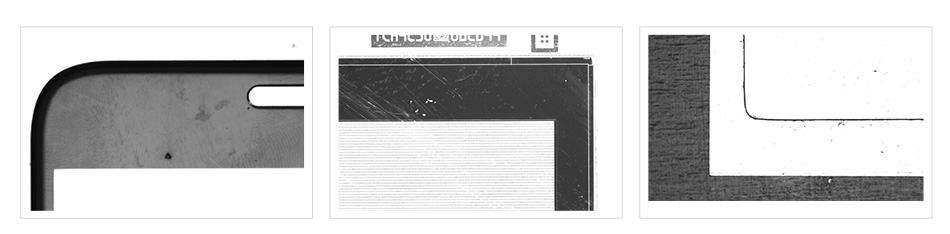
LCM- CG Process Section
Application: This section is mainly used for the process of CG cover plate in LCM. A border ink and decorative logo are screen printed on the surface of the transparent glass cover plate. Usually, screen printing and offset printing are used. High precision vision positioning system is required before screen printing to locate the four edges of the glass.
Imaging System Configuration:
- Camera: 1.3m 1/3″ cameras (5 units)
- Lens: WWL10-110AT/CT, CL20-65CT/633BP
- Illumination: Point light source or backlight source
- COOLENS advantage: COOLENS is the first in China to customize the pen-style all-in-one machine that integrates a simulated camera and telecentric lens for the CG process application, perfectly solving the space limitations faced by customers using multiple cameras for positioning and grabbing edges in a small space. The number of pen-style all-in-one machines supplied by Clearview, the leading CG manufacturer in China, has reached 5000+. It is mainly used for visual positioning of CG screen printing and early multi-camera glass cover plate measurement.
LCM – Screen full bonding
Application: This process is mainly used to closely bond the panel and the CG cover plate together using a transparent OCA optical adhesive in a vacuum wall environment. There are two types of bonding, soft-to-hard bonding between OCA and CG, and hard-to-hard bonding between CG & OCA and panel. This stage is the largest application in the whole LCM process in terms of the demand for vision lenses, with up to 128 camera lenses required for a single bonding line.
Imaging System Configuration:
- Camera: 12MP 1/1.7″
- Lens: 0.2~0.25x, MFA118-S25/35, WWT118-025-108
- Illumination: coaxial light, infrared ring light, or backlight
- Resolution: 0.05mm
LCM——Backlight Lamination Process
Application: This process is mainly used to produce the BLU backlight. A series of optical film materials, such as the support base film, reflector, light bar, light guide plate, diffusion film, brightness enhancement film, and light blocking tape, are assembled through visual positioning to provide a uniform backlight source for the entire display panel. The positioning resolution requirement is relatively low at around 0.1mm. OLED products do not require a BLU because they are self-illuminating. Currently, only some mid-sized displays still use the LCD plus backlight method.
Imaging System Configuration:
- Camera: 6.0MP 1/1.8″ cameras
- Lens: 25mm lens
- Illumination: Backlight
LCM——Backlight Assembly
Application: The backlight assembly is the final assembly process in LCM production, where the BLU and CG-attached panels are put together.
Imaging System Configuration:
- Camera: 12.0MP 1/1.7″
- Lens: MFA118-S50V2
- Illumination: Infrared backlight
The LCM Mura Dot Lighting Inspection is the final shipment inspection in the LCM production process. It is similar to the previous CT dot lighting test, but it focuses on detecting the uneven color of the Module display and calculates correction parameters based on the compensation algorithm. The correction parameters are then burned into the storage chip, ensuring the uniformity requirements of the Module display. The Imaging System configuration is the same as the CT dot lighting test.
