
Machine vision system refers to the process of converting the captured target into image signals and transmitting them to a dedicated image processing system through machine vision products (i.e. image capture devices, which are divided into CMOS and CCD), and converting them into digital signals according to information such as pixel distribution, brightness, and color. The image processing system performs various operations on these signals to extract the characteristics of the target and then controls the equipment on site according to the judgment results.
The key components of a machine vision system
Machine vision systems are mainly composed of image acquisition units, image information processing and recognition units, result display units, and visual system control units. The image acquisition unit obtains the image information of the target object to be measured and transmits it to the image information processing and recognition unit. Since the machine vision system emphasizes accuracy and speed, the image acquisition unit is required to provide clear images in a timely and accurate manner. Only in this way can the image information processing and recognition unit obtain correct results in a relatively short time. The image acquisition unit is generally composed of a light source, a lens, a digital camera, and an image acquisition card. The acquisition process can be simply described as the digital camera shooting the target object and converting it into an image signal under the condition of illumination provided by the light source, and then transmitting it to the image information processing and recognition unit through the image acquisition card. The image information processing and recognition unit performs various operations on the grayscale distribution, brightness and color of the image, extracts the relevant features of the target object, completes the measurement, recognition and NG (no) judgment of the target object, and provides its judgment conclusion to the visual system control unit. The visual system control unit controls the on-site equipment according to the judgment conclusion to realize the corresponding control operation of the target object.
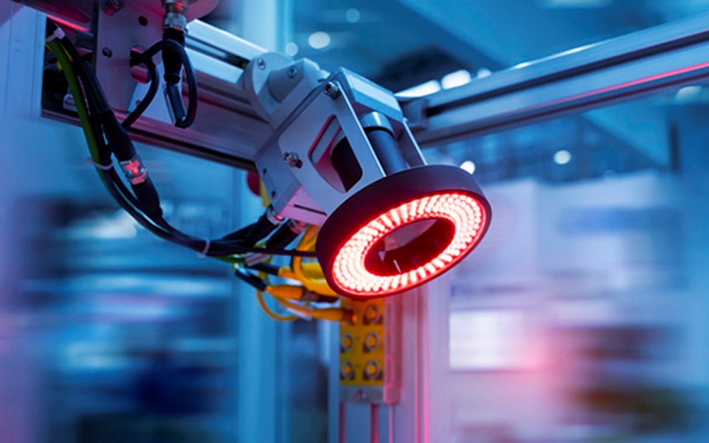
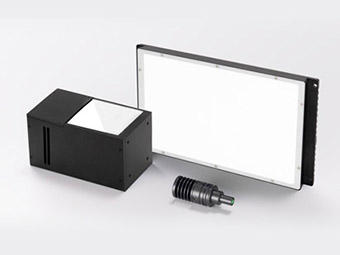
Illumination
An imaging accessory, it often plays a vital role in the quality of imaging. LED lights of various shapes, high-color fluorescent lights, fiber optic halogen lamps, etc. can be used as light sources.
Read related post> Machine Vision Light Source Overview
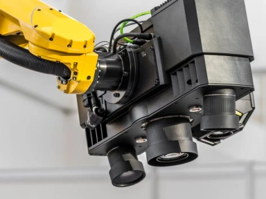
Industrial camera
It belongs to an imaging device. Usually, the visual system is composed of one or more imaging systems. If there are multiple cameras, the image card can be switched to obtain image data, or synchronous control can be used to obtain the food of multiple camera channels at the same time. According to the needs of the application, the camera can output standard monochrome video (RS-170°CCTR), composite signal (YCO.RGB) signal, or non-standard progressive scan signal, line scan signal, high-resolution signal, etc.
Read related post> Mastering Machine Vision: How to Select the Ideal Industrial Camera?
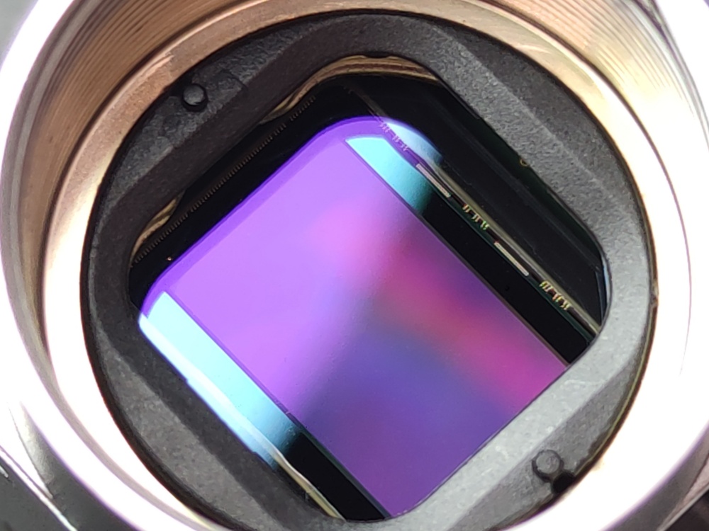
Sensors
Usually in the form of fiber optic switches, proximity switches, etc., are used to determine the position and state of the object being used. Tell the image sensor to perform correct acquisition.
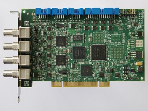
Frame grabber
Usually installed in the computer in the form of a plug-in card, the main job of the image acquisition card is to transmit the image detected by the camera to the computer host, it converts the analog or digital signal from the camera or a certain format of image data stream. At the same time, it can control some parameters of the camera, such as trigger signal, exposure, integration time, shutter speed, etc. Usually, different types of cameras have different hardware structures of image acquisition cards, and also different bus forms, such as PCI. PCI64. Compact PCI, PC104. ISA.
Computing platform
The computer is the core of a PC-based visual system. Its function is to complete the processing of image data and most of the control logic. For detection-type applications, a higher-frequency CPU is usually required, which can reduce the processing time. At the same time, in order to reduce the interference of electromagnetic, vibration, dust, temperature, etc. in industrial sites, industrial-grade computers must be selected.
Processing software
Machine vision software is used to complete the processing of input image data, and then obtain the result through certain calculations. The output result may be PASS/FAIL signal, coordinate position, string, etc. Common machine vision software appears in the form of C/C++ image library, ActiveX control, graphical programming environment, etc. It can be dedicated (such as only for LCD detection, BGA detection, template alignment, etc.), or it can be applicable (including positioning, measurement, barcode/character recognition, spot detection, etc.).
Control unit (including I/O, motion control, level conversion unit, etc.)
The visual software completes the image analysis (unless it is only used for monitoring), and then needs to communicate with the external unit to complete the control of the production process. Simple control can directly use the I/O of some image acquisition cards, while relatively complex logic and motion control must rely on additional programmable logic control units and motion control cards to achieve the necessary actions.
 |
 |
 |
 |
 |
 |
The main workflow of a complete machine vision system
- The positioning detector detects that the object has moved close to the center of the camera system’s field of view and sends a trigger pulse to the imaging component.
- The imaging component sends a start pulse to the camera and lighting system respectively according to the pre-set program and delay.
- The camera stops the current scan and restarts the scan of a new frame, or the camera is in a waiting state before the start pulse arrives, and then starts a new frame scan after the start pulse arrives.
- Before the camera starts a new frame scan, the exposure mechanism is turned on. The exposure time can be set in advance.
- Another starting pulse turns on the lighting, and the light on time should match the camera’s exposure time.
- After the camera is exposed, the scanning and output of a frame of image officially begins.
- The image acquisition part receives the analog video signal and then digitizes it through AD (a converter that converts analog signals into digital signals), or directly receives the digital video data digitized by the camera.
- The image acquisition part stores the digital image in the processor or computer’s memory.
- The processor processes, analyzes, and identifies the image to obtain measurement results or logical control values.
- The processing results control the action of the assembly line, perform positioning, correct motion errors, etc.
From the above workflow, it can be seen that the machine vision system is a relatively complex system. Most of the monitored objects are moving. Since the matching and coordinated actions of the machine vision system and the moving objects have to be pin-point precise, strict requirements are placed on the action time and processing speed of each part of the system. In some application fields (such as robots, flying object guidance, etc.),this requirement extends to the weight, volume, and power consumption of the vision systems.
The typical workflow of imaging process
Image capture
The function of the sensor is to collect external information, that is, to capture images. The target object is illuminated by a light source, and the reflected light represents the relevant information of the measured target, which is the same as the principle of human eyes seeing objects. The reflected light enters the camera lens, and the process of imaging by the camera is called capturing the image.
Image transmission
Transmitting image data involves a lot of communication, including communication with acquisition cards and networks.
Image processing
Image processing can be divided into preprocessing and measurement processing. Preprocessing is to correct the brightness of the image, extract and filter the color, and convert the binary data, that is, to convert the collected image into information that can be recognized by the computer. Measurement processing first matches or collects information for the part that needs data collection, and then judges the collected data. For example, the detection of size, that is, each size needs to have a tolerance upper and lower limit judgment, which is completed by software, that is, the core measurement processing is to perform measurement judgment processing, which is usually completed by the hardware acquisition card and software.
Information output
Information is output to the executor. Since the machine vision system itself belongs to the collector, it does not have the ability to execute, but it is the eyes and judgment basis of the executor, so it will pass the captured information to a third party.
Case analysis: the visual inspection process of pharmaceutical glass bottles.

Inspection requirements
The inspection system detects defects in pharmaceutical glass bottles (including white bottles, brown bottles and bottles with scales). The inspection information of pharmaceutical glass bottles is shown in Figure 1-3. The height of the inspected bottle is 15~150mm, and the inspection speed is required to be 0~280 per minute.
Inspection parameters
- Size: including bottle height, bottle body outer diameter, bottle mouth outer diameter, bottle mouth height, etc.
- Bottle body appearance defects: including bubbles, impurities, wrinkles, horizontal and vertical stripes, adhesion, stones, cracks, scratches, scratches, and obvious oil stains, fingerprints, etc.
- Bottle bottom defects: from the side, it can be photographed that the bottle bottom is uneven, thorns, and biased bottom.
- Flat shoulder defects: including oblique shoulders, crooked bottles, and appearance defects similar to the bottle body.
- The inspection of the bottle mouth refers to the inspection of notches, cracks, uneven round mouths, etc. in addition to the types of defects in the appearance of the bottle body.
Read related post> How Telecentric Lenses Are Used for Liquid Pharmaceutical Inspection
Monitoring system demand analysis
- In order to detect the defects of the entire bottle body, four cameras should be used to detect from four directions to ensure that the effective detection area of each camera is 90°.
- In order to be applicable to the detection of bottles of various colors, the system uses a high-brightness backlight source to illuminate from behind the glass bottle.
- In order to adapt to the detection of bottles of various specifications, the system uses a variable-focus lens to ensure that bottles of various specifications can occupy the entire field of view.
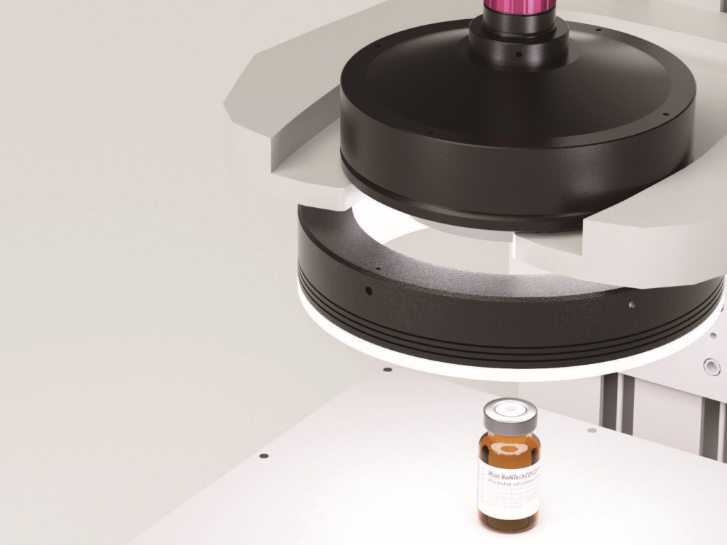
- A separate station is used to detect the defects of the bottle mouth. In order to better capture the defects of the bottle mouth, a special bowl-shaped light source is specially designed to illuminate the bottle mouth.
When the glass bottle passes on the conveyor belt, the system uses an external trigger method to accurately capture the images of the four sides and one front of the glass bottle at a fixed position, and then transmits the image to two high-performance processors for processing and analysis, and then summarizes the results on a server for unified control and display.
Functional analysis of the visual system
- Image capture function.
- Dynamically adjust the image magnification ratio according to different product specifications.
- Dynamically set camera parameters according to the on-site environment.
- Capture images based on the external trigger of the product arrival signal to adapt to the changes in the on-site machine speed.
- Standard template training function.
- Provide a friendly and convenient template training interactive interface.
- Detect parameters separately according to different detection areas of the product.
- According to the shape characteristics of the bottle, provide the setting of detection polygon area so that each area of the bottle can be effectively detected.
- Product detection function.
- Use the standard positioning module to position the bottle, solve the problem of bottle tilting due to the conveyor belt, and improve the accuracy of the detection size.
- Adjust the overall brightness of the bottle through preprocessing to obtain the actual processing area.
- Process the actual area, eliminate interference, obtain the error area, and classify the errors.
- Error classification function.
- Determine the defect type based on the defect shape characteristics and the location of the defect.
- Detect parameters separately according to different detection areas of the product.
System display function
-
- Real-time display of error/defects.
- Automatic accounting of error types.
- Convenient logging of historical records and comparison with actual error products.
- All graphical interface interactions are realized during template setting, which is convenient for operation.
- Real-time display of error/defects.
